Maker: Venus de Venus

My printer ETA just finished a sculpture I designed a while back, which I called “Venus de Venus”. It stands 27cm tall, and took 11 1/2 hours to print, the largest object I’ve printed on ETA thus far.

A little back story on this piece. I had a class on wood and metal working a while back, and for that class I carved a statue of Venus de Milo, an ancient greek sculpture, with a little difference.
The head is an oblate spheroid, to represent the planet Venus, from whence Women are said to have originated from, for there are two mysteries that have always, and presumably always will elude man, and that is the eternity of space, and Women in general.

Venus de Venus (24)

A close-up of my hand carved piece

TL:DR Classical Medium vs Contemporary Medium, the ongoing battle of mediums since classical times.

Until next time,

Adithyaa

Projects, Plans and Procrastination

Heello, Sunday!


It’s good to see you again, I feel melancholic when I don’t update my blog or write poetry, and I haven’t done either in such a long time now. Since my last post, quite a lot of things have happened. I finished another year in college, started an internship, and organized my lab.

IMG_20170521_080754_HDR

Well, Organized for the most part…

I’ve earned the title of “Scrap Collector”, to all those who know me well, and it is a title well earned. I’ve accumulated a hoard of parts, gadgets, stationary, components, bric-a-brac, and scraps for over a decade, and it’s reached a point where I had to toss out all the things I perceived were not immediately useful to me. My remaining collection is still somewhat wasteful, albeit neatly organized now, and it includes but not limited to, a kilo of plastic strip files, 10kg of e-waste, miscellaneous toxic chemicals and mixing pots, fasteners and random tools, more piping and hose than a Shakespearean reproduction, enough plasticine clay to build a kindergarten, a hot pink toilet seat, and some of my lost marbles (only 3Kg of them).

Regardless of the phrase “One man’s trash is another man’s treasure”, I believe the 10-year’s worth of spring cleaning was slightly overdue.

Project Eta (134).jpg

ETA, Chilling on the bay window

On the project front, I’ve begun Plan Wololo, a plan to convert Project ETA’s HBot kinematics to CoreXY, using non crossed belts. I’ve already done the CAD work, and I should receive all the parts in a few days. While designing ETA, I’d made sure to include the tolerances for when I transition to CoreXY kinematics in case HBOT’s accuracy was insufficient, so it should go somewhat smoothly.

WhatsApp Image 2017-05-21 at 08.17.07

Various random concepts for the moon clock

I’ve also started Project Moon clock, a desk or wall mounted gadget which indicates the current phase of the moon, for those who don’t like stepping outside or have cloudy weather. It’ll have a little ball representing the moon, and will use a NodeMCU and a servo motor to rotate said mini-Moon, and indicate how lit it is. It’s a quick little project, as a present for someone.

That’s all for now, but I am going to restart weekly updates on this blog of mine, so please, stay tuned and let me know thy thoughts.


Signing off,

Adithyaa~

Project: FFF 3D Printer “Eta” Part 9

Hello, SUNDAY!

Whew, it’s been an unfortunately long time since my last post, I’ve had to move my base of operations and un-discombobulate everything, and much is still a mess. However, this move comes with it’s benefits, as now I have a dedicated areas for my computing, electronics, metal, resin, wood, plastic, and 3D printing work. This compartmentalization allows me to quickly finish tasks in any field, so I should be clipping along speedily henceforth.

On the topic at hand, Printer ETA is finally fully online and mechanically sound (for the most part)! I had to disassemble Eta to move it, so I used this opportunity to upgrade the X & Y axes with shiny new bearings and carriages, which now means I have more accurate and precise prints.

Here are the upgrades I’ve installed,

project-eta-126

Printer feed is a sensitive area, and feeding dirty or dusty filament is asking for a jam. To fix this, I hacked together a rudimentary but very effective filament cleaner (could be used to oil it too :] )

project-eta-127

New Y axis carriages, printed in ABS by my dear friend Balaji, equipped with 3 LM8UU each to counter the HBOT mechanism’s XY torque.

project-eta-128

A new belt clamp, to allow me to remove/adjust the hotend without loosening the belt.

project-eta-129

As much as I like to wave around my successes, I’m open with my failures, so that others may gain from it at the very least. Here, I miscalculated the offset between the two belts, leading to a bend in one side. Luckily, this did not affect print quality.

Moving forth, I’ve setup my printer on the bay window in my room. Even though my printer’s bearings and steppers are extremely quiet, I can detect it’s movements by placing my ear to the walls even a floor away due to it’s discreet vibrations transmitted through the building. Truly a highly advanced monitoring system.

Now that we’re done with the nerd stuff, we move onto seeing what I’ve been printing!

I’ve been calibrating and printing, and Eta’s functional enough at this point for me to simply select the print job and leave. That said, keep your eyes and ears on your printers, they apparently  suffer from separation anxiety and are prone to spontaneous self injury.

I’ve also  started using very watered down PVA white glue to coat the print surface, and I’m extremely happy with it. With plain heated glass, I had to amp up the temperature to get anything to stick, and even then, lines getting peeled off were far too common on even small prints. However, first coat of PVA I slathered on instantly fixed all of that, and parts detach perfectly afterwards. If I need to reapply the coating, I simply take the glass out, pour water over it, and scrub it after a few minutes, then reapply the coating with a sponge.

I’m looking forward to working on many projects using Eta, so keep your sensors scanning the horizon for more to come!

That’s it for now, but stay tuned, there may be additional posts flying in very soon!

Singing off,

~Adithyaa~


Project: FFF 3D Printer “Eta” Test print Timelapse

Hello, Sunday!

We meet once more, this time to spectate the video of mine 3D printer, Eta, printing a tiny calibration cube.

It still has room for improvement, but what do you think?

Project: FFF 3D Printer “Eta” Part 8

Hello, Sunday!

So Eta was on hold for a while as I was awaiting a few parts, and where I left off last I was having hotend problems. It was a Chinese clone of the E3D v5 and it was jamming harder than an amateur jazz band, and I had to blowtorch solidified PLA out of it several times.

However, my grandfather, Jairam Thatha came to my rescue and brought me a E3D lite6 from America. The lite6 installed easily and worked like a charm, easily extruding PLA once calibrated. However, as you all should know, problems present themselves like hydras, lop off a head and two more shall sprout. In this case, it was Z axis wobbliness!

Project Eta (123).jpg

I used LM8UUs fixed into the Z axis bed platform with a little hotglue, so there was a minuscule amount of play in the fitting, but this meant that the platform could pitch back and forth about ~5mm. When the threaded studding rods lifted or lowered the platform, it would cause a slight variance in the height of the bed. Not by much, but I’m trying to lay down plastic lines 0.4mm thick, so a minute wobble is all you need for it to not work.

Hence, Once more, we venture into the fray! IE,  SJP road.

Having returned from SP road with flanged bearings, I set about installing them into place in Eta. They didn’t have many flanged bearings in stock, so I just about managed to get two LMK8UUs and two LMF8UUs, which works out fine for me.


I also had a small issue where the bowden tube & hotend cables kept flopping over, so I devised a highly sophisticated mechanical construct to keep it upright.

project-eta-121

Ahem…

The flanged bearings nearly completely eradicated the the wobble, and while I was installing them I also straightened out the Z threaded rods by placing them against a pane of glass and gently rapping them while turning them to find the high spots. #highlyadvancedproblemresolution

I’m certain no one found the the double the in the prior paragraph. 🙂

Next, I spent a lot of time just banging about Marlin’s parameters, and trying to bludgeon the bed leveling code to work. No matter what I try, the Z axis kept getting muddled. I made a Z probe using contacts glued to the bed’s glass, and the nozzle itself as the contact, which worked splendidly as long as the nozzle isn’t covered with plastic. However, the leveling code itself is still non-functional. Any suggestions welcome.

I started Eta at the start of this year, just after the clock struck 0000, I decided to go over to my computer and resume some reading I was doing on 3D printers, and then I decided to go along and design and build one. 5 months, on and off designing and reading about them, and then 6 months buying parts, waiting on deliveries, and prototyping.

Finally, HenriETA, my printer, IS COMPLETED! nearly, at least. I still need to add-on a few parts, like a print cooling fan, but for the moment, it’s functional and that makes me happy. I’d like to thank my parents, Jairam thatha, all Indian online electronic parts stores, and the entire opensource community on the internet. Wouldn’t have been possible without all you guys =)

Stay tuned for the next post, which will have a talk about Eta over a timelapse of it printing a test object 😀

Singing out,

Adithyaa~


Cosplay: Making Blades (with the Sword of Altaïr )

Hello, Sunday!

So, I’ve had a lot of people ask me on how to make blades, specifically swords, spear heads, etc. for costume and cosplay purposes. One of the easiest ways to do so, is to simply make them out of wood, as discussed in my Deadpool Swords Buildlog.

However, for all its strength and ease of access, wood isn’t a great material to use. It’s weak in thin sections, heavy, has grains to take into account, and most of all, necessitates usage of power tools. It’s still possible to use a hand file and try to sand an edge, but if you’ve got to do 4 edges on a diamond cross-section sword, you’ll be emptying your tank of patience and energy, not to mention carpal tunnel for the sake of cosplay. Furthermore, some cons discourage usage of wood, due to its hardness and weight, so it’s a safer alternative to go with foams and plastics.

My preferred method to blade making is the sandwich method, which took some trial and error for me to perfect. The concept is simple enough, 3 or so layers of thin plastic, with the middle layer made hollow to embed steel wire into for strength. With the tests I conducted using PVC Foamboard (Sunboard), I found that even 3 layers of 3mm(actually 2.7mm) sunboard bonded using epoxy were very floppy, and broken easily. However, the sandwich method gives it strength and stiffness without compromising on cost or ease of construction.

Here are a few pictures of some of the blades I made using this method-

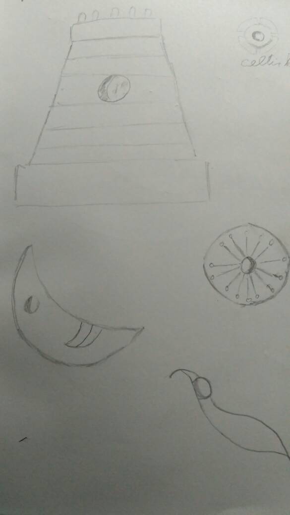
To illustrate how it works, it’s time for a MS Paint diagram!

Sandwich Blades.png

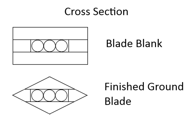
The blade blank is about 35% through the sword construction process, and when the filing and sanding is finished you have the final blade’s shape.

As you can see, you basically sandwich several layers of plastic with a bit of wire in the middle, and then grind it down with a file to produce the sword shape. It’s easier than you’d think, here’s how it’s made.

You’ll need-

  • Sunboard(3 & 5mm depending on your blade’s size and thickness)
  • GI Wire(3 or 5mm depending on your center layer’s thickness)
  • Epoxy (more is better than less)
  • Paints, Primer, clear coat, etc.
  • Any sword specific detailing

Tools

  • Steel or wooden ruler, 60cm or 100cm
  • utility knife
  • Square or half round Bastard file
  • Sandpaper(80, 220, and 400 grit)
  • Clamps or weights
  • Masking tape

Procedure

You start by measuring out the dimensions of your sword. I’ll be describing how I made Altair’s sword.

mr883015

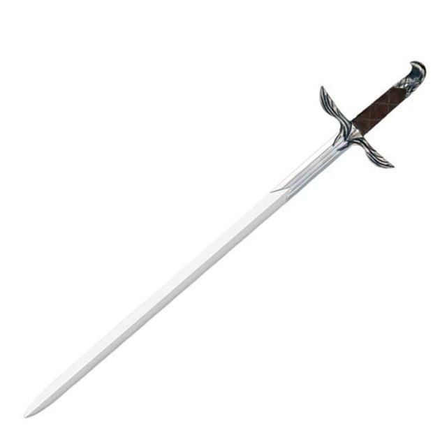
The blade is approximately 70cm long, and including the handle it becomes 82cm

So my sword is 82 cm long from tip to pommel, 3 cm wide, and about 1 cm thick. I started by cutting out the top and bottom sunboard strips, 82 cm x 3 cm. Use the ruler and run the utility knife along it multiple times to make sure that the cut comes out as straight as possible. The more care you take here, the cleaner and more accurate your final blade will be.

Next, I cut out two strips for the middle of the blade. Considering that the GI wire goes in the center of the blade, we’ll only need narrow strips, hence I cut two 82 cm x 1 cm strips. I then cut 4 lengths of 3mm GI wire 75 cm long, and straightened them by hand until I could roll them on the floor. The GI wire must run from the end of the handle upto a few centimeters from the tip for the blade to be strong, but the tip itself must be solid sunboard so that it can be tapered without showing the wires. I just used another piece of 5 cm x 1 cm sunboard when sandwiching the blade.

NOTE- I discovered this the hard way, but you must ensure that the GI wire is thinner than the foamboard you’re using, else it can cause the blade to bulge. If you still need the strength, you can clamp the blade blank between 2 stiff planks as the epoxy is curing to compress the foam.

Once you have the strips of sunboard and the wires cut out and straight, begin preparing to epoxy the blade. Measure the width of the 4 wires, and mark two lines on the bottom wide strip of sunboard. These will help you to align the side strips so that the wires have enough space to sit inside the blade.

Now begin the process of epoxying the 82x1cm side strips onto the 82x3cm base strip. Do this step outside, it gets messy. Take a little sandpaper and scuff up the surface of the sunboard a little. Mix a generous amount of epoxy, and apply it outside the two lines you marked on the base strip earlier, and onto the middle section only at the tip and pommel of the sword. Then take the 1cm wide strips, and press them into the epoxy. Work quickly, the epoxy will set soon, and it pays to have everything properly arranged so that you can quickly work without having to search for anything. Be generous with the epoxy, but use an ice cream stick to scrape any excessive oozing away. Better more than less, or your blade will delaminate. You can use masking tape to keep your strips aligned as they’re being clamped.

You can see now that you’re creating a channel in the middle of the blade for the wire to be placed into. Place a short strip of sunboard on either end of the channel, so that the tip and pommel are solid plastic and epoxy. Weigh and clamp down the bottom and middle layers, then go and play a video game for an hour.

Once the epoxy has cured to handling strength, take the GI wire rods cut and straightened earlier, and mix up a large amount of epoxy. More is always better, as you’ll end up using a lot in this step. Take an ice cream stick and spread epoxy into the center channel, and onto the top of the side strips. After you’ve got an even covering, press your wires into the center channel, and make sure they’re well seated into the epoxy. Cover the wires and sides with more epoxy, then place the top strip onto it, and wrap strips of tape around the blade to keep it aligned. Then clamp or weigh it strongly between two planks, and leave it for 24 hrs. Avoid placing weights or clamps directly on to the foam, as you’ll leave a mark which is difficult to get rid off later.

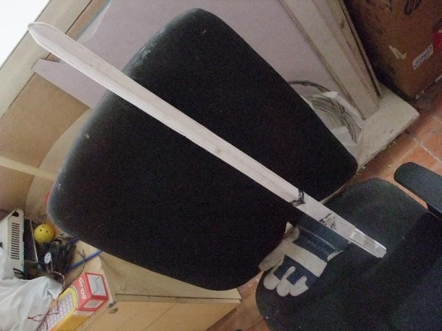
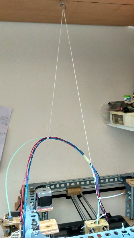
Once the epoxy has cured, you’ll be left with something resembling this-

Master Sword WIP (1).JPG

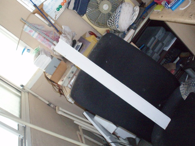
This is the blade blank for my TLoZ:TP Master Sword. It’s about 7cm x 80 cm long, not including the 20cm threaded steel rods poking out the top. Here I plan to make the handle by casting it, hence I didn’t extend the sunboard over the handle. I had to use 6mm threaded rods to give it strength, due to the sheer size of the blade

This is the blade blank, a solid billet which can be carved into the sword. Up next, everyone’s favorite step, Sanding and grinding!

*Collective groaning ensues*

Yes yes, but this step is necessary, so have at it and you’ll be done in a day. In the event that you ended up using wire that was too thick, or didn’t clamp properly, then you’ll end up with splits and delamination. Don’t worry, you don’t have to start over, you can fix this by keeping the blade split side up, pouring superglue generously into the cracks, then strongly clamping it down for at least 1/2 hr.

Sword of Altair (1).JPG

Clamp the blank to a table, mark out guidelines to aid your sanding. Note the wood used in the clamps to prevent them from leaving marks. Keep filing evenly down the blade, removing material in passes rather than trying to grind it off all at once. If you don’t have a file, you can stick sandpaper to a strip of wood and use that instead. Keep sanding until you get the desired form, then sight down the blade to ensure that it’s straight and clean. The wire has a certain degree of stiffness, so if the sword is bent it’s an easy affair to straighten it out with your hands.

Sword of Altair (3).JPG

My handle was rather flat, so I added a few strips of sunboard onto it and sanded them round.

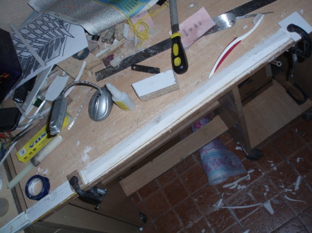
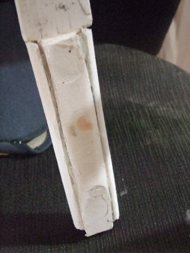
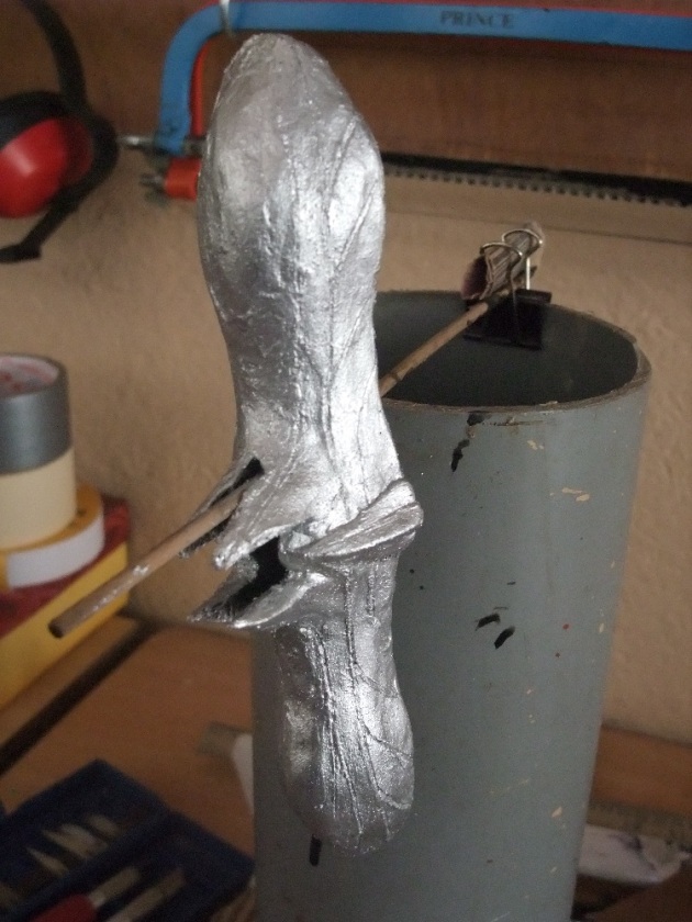
Finish sanding by using the finer grits to knock off any imperfections, and prepare to prime the surface.Your finished blade form should look somewhat like this.

sword-of-altair-2

You can see the layer lines in this image, these lines help when filing the edge because you can see if they’re straight or not to check the angle the edge is currently at.

The next step is making the hilt, but that is another a whole new chimichanga, so we’ll leave that for another day.

Sword of Altair (4).JPG

Here is the nearly finished hilt, just needs a little touch up and distressing

The rest is pretty straightforward, nothing to really teach here. Paint the blade with primer, sand with 400 grit, prime, sand, prime, paint with silver acrylic paints or spray paints, distress with diluted black acrylic, and clear coat x2. Painting the blade is the comparatively easy part. To finish, I wrapped the hilt with black rexine and glued it down.

aaand, DONE!

That sums up the entire process of making a sword blade via the sandwich technique, I hope that you found this guide useful and informative. If you do ever use this method, do let me know how it works out for you, along with any pictures 🙂

Thank you for your time, and see you all next week at comic con!

Signing off,

~Adithyaa~

Project: FFF 3D Printer “Eta” Part 7

Hello Sunday!

I’ve been a bit busy repelling the fusillade that is life, with varying success. Those of whom live in close proximity to me may have experienced paranormal sounds and or mumbled exclamations emanating from my lab-cave, but worry not, its just me trying to get my printer online.

A Series of Iterative Incidents of Murphy’s Law

Where I left off, It was 4 weeks ago (Five weeks now, time really does fly), and I had just finished the physical construction of my printer. Most of it, that is. I started by installing the endstops onto the smooth rods. I used microswitches for the Xmin, Ymin,Ymax, and Zmax endstops, and an opto endstop for the Zmin, to ensure accuracy. As my system is a Hbot, I decided to use both min and max endstops to help prevent any accidental crashes.

project-eta-99

I attached them using zip ties and strips of latex cut from surgical gloves,  to prevent them from slipping on the smooth rods.

All the wire I used was twisted for convenience, neatness, and signal clarity. Next, I began configuring the software tool chain for controlling my printer. I used Marlin, an open source firmware for the RAMPS 1.4 control board, Pronterface for direct printer control from my computer, and Cura for slicing.

Attempting to configure a printer is akin to teaching a baby how to move, and then trying to catch it as it bolts off the dinner table headfirst. Eta did ram her print head into the boundaries several times until I got it to understand which axes were which and which endstops applied to what, but it turned out all right with no damage.

MOSFETS and overthinking solutions

I spent a better part of my time planning figuring out how to power the obnoxiously large heated bed that I decided to use, due to its high rated amp consumption. 30A is no joke, and my lack of electrical engineering skills could very well jeopardize my printer, and possibly my continued presence in my house.

After much research, a good deal of headbanging and SP road trips, I finally settled on using three IRLB8743 Mosfets to switch the current to my bed. The RPF ‘fet on my ramps board was simply unsuitable for the task, so I didn’t even try it out in fear of combustion. I soldered the fets to a PCB, wired them up in parallel using thick housing wiring, added a 10k resistor to keep gate at ground, and slapped the largest heatsinks the shop had to offer on fets.

It’s pretty self explanatory what’s going on here. To all of those facepalming about why I’ve mounted a PCB in a metal box, its so that it is less likely to catch fire. The PCB is mounted on a biscuit of wood, and everything is fixed down. With zipties and hot glue. Clearly brilliant engineering.

project-eta-119

A rough diagram I drew when I was visualizing how the mosfet circuit would be made.

Finally, I bolted down all the connectors, checked every joint and connection thrice, and finally turned on the 12v 50A PSU and activated the heated bed!

But nothing happened. Or more accurately, nothing bad happened. I ran the heated bed for several tests, it heated up properly, no melting, no fumes, nothing. The mosfets were room temperature even after running the bed for 30 min. I somewhat suspect that the heated bed is drawing approx. 14-18a, judging by ohm’s law and the PSU’s fan’s duty cycle. On the flip side, the system I engineered could possibly take up to atleast 60a at 12v.

Better more than less, I suppose.

More software tweaking was done, I installed the LCD control screen into a large box, and hooked it up as well. The fourth box as enough space for more additions as well, like an E-Stop button or arduino.

This slideshow requires JavaScript.

Here we encounter another incident of Murphy’s law, where my computer decides to crash. Permanently. After a quick series of diagnostic tests, I decided to abandon the 14 year old PC, and instead use an old laptop I had laying around, so that was quickly solved. I like to use Linux mint for my lab computers, due to its lightweight, features and speed.

Worse congestion than a cold in Monday traffic

I’m using a e3D v6 clone, featuring an all metal body. I hooked up the hotend, bowden tube, and the extruder body, and started running configuration tests. The hot end heated up, fan ran, and everything was peachy until I tried to extruding plastic. The filament went smoothly in, and then the extruder gear began grinding like a lion with anxiety. I unwound the filament, and then tried pushing it through manually, and it kept hitting something inside the hot end.

If that wasn’t bad enough, thermal creep started, and the plastic melted in the colder part of the hotend, which is bad because that can’t be cleared easily. With my plastic firmly frozen in the upper heatsink, I was forced to disassemble the hotend to clean the jam, and use a blowtorch to burn out the filament in the heater block and nozzle.

This proceeded to occur with mildly different scenarios three more times. Finally, after the pneumatic press-fit joint proceeded to join the rest of the hot end in failing miserably, I decided that I need to take a short haitus from building Eta, while I wait for the replacement parts to arrive.

I estimate that I’m about 90% done with Eta, as I just need to install the new hotend, calibrate, and slap on the final safety features. Until then, I’ll be working on other projects, Comic con is approaching!

Signing off,

Adithyaa~

MiniMake: Benchtop PSU

Hello Sunday!

So as I’m working on Project Eta right now, I need a source of power while I’m prototyping. Historically, I’ve been using 9v batteries and AA battery holders to provide power while prototyping, but obviously, that is less than perfect as a solution. So I had a couple old computer ATX power supplies laying around, and I decided to turn one of them into a benchtop power supply, as these handy little supplies provide 12v, 5v and 3.3v in neatly regulated cables. This project takes less than a weekend to finish,  and presumes you have basic skills with soldering connections and a grounded understanding of how electricity works.

WARNING! POWER SUPPLY UNITS CONVERT WALL OUTLET ELECTRICITY INTO LOW VOLTAGE HIGH CURRENT. ELECTROCUTION HAZARD AND DAMAGE TO YOURSELF/YOUR HOUSE’S WIRING/YOUR PSU AND YOUR PET GERBIL IS POSSIBLE. UNDERTAKE THIS PROJECT ONLY IF YOU KNOW WHAT YOU ARE DOING. KIDS, DON’T TRY THIS AT HOME.

Components

  • Computer PSU, 2nd hand works well, ATX preferred.
  • LED/bulb for indicator
  • Switches
  • 2.1mm plugs, screw fit connectors, crocodile clips, etc.
  • Heat shrink tubing & solder

Tools

  • Multimeter
  • Drill
  • Sheet metal snips and tools
  • Soldering Iron
  • Wire Stripper

On Choosing ATX PSUs-

Most PSUs should work ATX works well because they usually have a bit more headroom for circulation, and they’re the most common and cheap. It’s advisable to use a second hand PSU for this project, as long as it works. Some old PSUs require a minimum load on the 5v line in order to properly regulate the 12v line. This can be fixed by adding a resistor onto the 5v line, but at low current applications it shouldn’t be an issue.

Benchtop PSU (2)

Here’s my PSU’s specs, and I doubt I’d be reaching anywhere near the limits

Procedure

Start by unplugging your PSU and leave it alone for around 15min, just in case the capacitors have any remaining charge in them. Remember to exercise caution and possibly even common sense while working.

Unscrew the 4 screws on the top of the box, and remove the upper shell. The PSU has two U shaped shells, one upper and one lower, which forms the body. The lower one has the electronics, fan, power port, and cables attached. If you want to paint your PSU afterwards, peel off the labels now, and give the upper shell a thorough scuffing with sandpaper, 120 should do it.

Now plan your layout for what you plan add to the box. I’m using 3 sets of crocodile clips, a 2.1mm jack for arduinos or the like, a 2.1mm port, a potentiometer, an indicator bulb and a power switch. You may want to adjust this depending on your anticipated usage, maybe using header ports instead of barrel plugs, your choice.

Use a marker or scriber to mark your layout, then use a drill to make the holes. Keeping a scrap of wood under the sheet metal as you’re drilling will prevent it getting dented or damaged as you drill. After drilling,  I used a pair of snips to cut a square hole for the main switch, and clean up the edges of the circular holes.

Benchtop PSU (3).JPG

Upper shell of the PSU, drilled and ready to receive the components.

After drilling the holes, give your box a gentle scuff of sandpaper to prepare it for painting. For my texture, I decided to go with hazard stripes, a lightning bolt and the word HAZARD on the top shell, and leave the lower shell as plain metal. I painted the entire box black with gesso primer, then I used 1in masking tape to create a diagonal masking pattern on the box. Using a paper cutter,  I cut out the details out of the masking tape strip, and then painted the entire shell lemon yellow.

Benchtop PSU (4).JPG

After the paint dries, peel off the tape, and behold your work. You can screw in your accessories at this point, I went with an old fairy light bulb for a mildly retro look, a potentiometer and a 2.1mm port.

connector_atx_pinout

Standard Pin layout for the thick wire bundle from your PSU, older PSUs use version 1, mine was v2

Next, we start the fun part, wiring. Observe the tangle of wires on your PSU, you’ll notice one thick bundle of around 20ish wires, and several thinner bundles. Use a wire cutter to cut the plugs off the thinner bundles. All the wires should be colour coded, although the colours vary depending on the manufacturer, but typically the yellow wires should be 12v, red is 5v and black is common. Use a multimeter to check just in case. Leave the PS_on, -12vdc, 5vsb and PWR_OK wires connected to the big plug for now, and cut all the 12v, 5v, 3.3v, and ground cables from the plugs as long as you can, pull them into the case and group them.

Benchtop PSU (5)

12v yellow, 5v red, ground black, 3.3v orange

Next, carefully observe which wires are PWR_OK, -12vdc, and 5vsb, and cut them from the plug. You can either snip these cables as close to the board as you can, or tie them up inside the case. The PS_ON wire is useful because when it is connected to ground, the PSU turns on. This cable is what we will connect to the power switch on the case. The 5vsb provides 5v dc at approx. 400ma even when the PSU is plugged in but off, so it can be used if you want to control the outputs with a micro-controller.

Next, we start soldering. I connected a ground cable and the PS_ON cable to the red main switch, and  I connected one of the 3.3v cables to my bulb, so that when the PS_ON switch is flipped the light comes on to indicate the PSU is live. Two 12v lines went to a pair of crocodile clips and a 2.1mm barrel plug. I used the potentiometer as voltage divider to control the power to one set of croc clips. I like to twist the wires around each other to keep them together, with a little ring of heat shrink at each end to prevent them unraveling. Remember to insert heat shrink before soldering!

Benchtop PSU (6).JPG

Once you’ve soldered all the wires you’re going to use, curl up the additional wires, zip tie them and push them to the side of the case. Remember, airflow is important inside the case to prevent overheating, so ensure that you haven’t blocked off the fan or its airflow path. Do a final test with a multimeter to check that all switches, plugs and wires function properly. Pull the crocodile clip wires out through the hole in the PSU case, and close up the case. Check that the tabs on either side of the upper shell properly align with the ones on the lower shell, and that its facing the right direction, and tighten the screws.

Thats it! Your PSU should be fully functional now, plug it in and give it a trial run. As a last minute feature, I glued a small strip of PVC foamboard (sunboard) to the rear of the case, and made some impressions in it so that I could clip my crocodile clips to it. This prevented the clips from accidentally touching and shorting out.

I hope you enjoyed this short MiniMake weekend project tutorial log, and I hope it was of use to you. If you’ve got any queries, please do leave a comment and I’ll reply as soon as I can and do consider sharing and subscribing for more weekly content.

Until next time,

Signing off,

~Adithyaa